Playing with the Raspberry Pi - Work Project
I’ve been wanting to do a hardware project for a while. After all, I like to tinker. Remember, I built my own spelunking headlamp out of fairly high powered LEDs. (Shame I don’t have photos… this was 2001/2, no cameras in those days I guess).
At work, we have a lot of servers and I thought it would be cool to do a hardware project that would be useful for one of my daily tasks - ensuring our systems are up and running (a responsibility I share with a few others at my company). Several months ago, I thought it would be cool to have a red flashing light whenever we got an alarm or other notice that something wasn’t quite right. This would be both cool and practical I thought - cool since red flashing lights are cool, and practical since, hey… a red flashing light means something is wrong, and one shouldn’t be bothering me, right?
I’ve thought about arduino and a few other platforms, but when the Raspberry Pi was finally obtainable, I decided to purchase one. The fact it ran a proper debian-style Linux distro was very enticing to me.
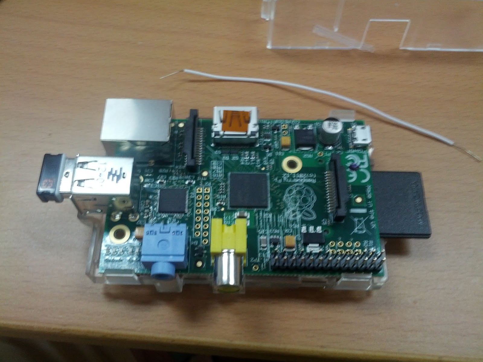
I was happy that installing the official Linux OS for Raspberry PI was painless. Just download the image, “burn” on the SD card, pop in, and wha la. But, just Linux running on this tiny machine wasn’t enough. I needed equipment.
Over the weekend, I headed to Sim Lim Tower - the place to get electrical components in Singapore.

The monitor was already in the office, but everything else was purchased. Some of the key items:
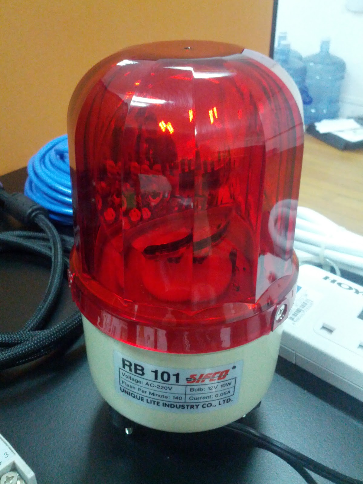
- 220V red flashing light - nothing says “oh crap” like a red flashing light, right?
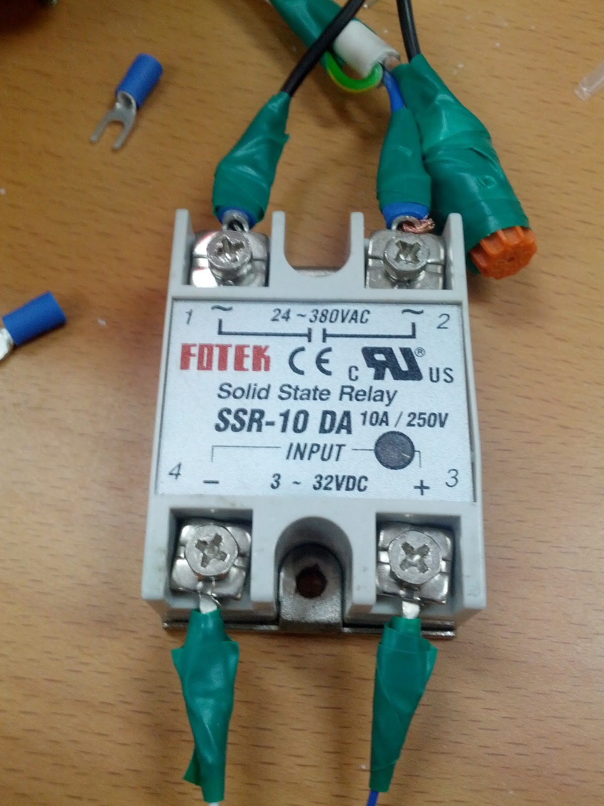
- Fotek SSR-10 DA Solid State Relay (10 Amps, 24V-380V loading, 3V-32V input)
The Solid State Relay
This cost S$19.50. The Raspberry Pi GPIO pins are rated at 3.3V, so this SSR offers an input range that works well with the Raspberry Pi. And of course, I needed a load voltage to support 220V as I wanted a red light that could be plugged into the wall (a 12V or 24V red light would be troublesome from a power source perspective).
The Red Light
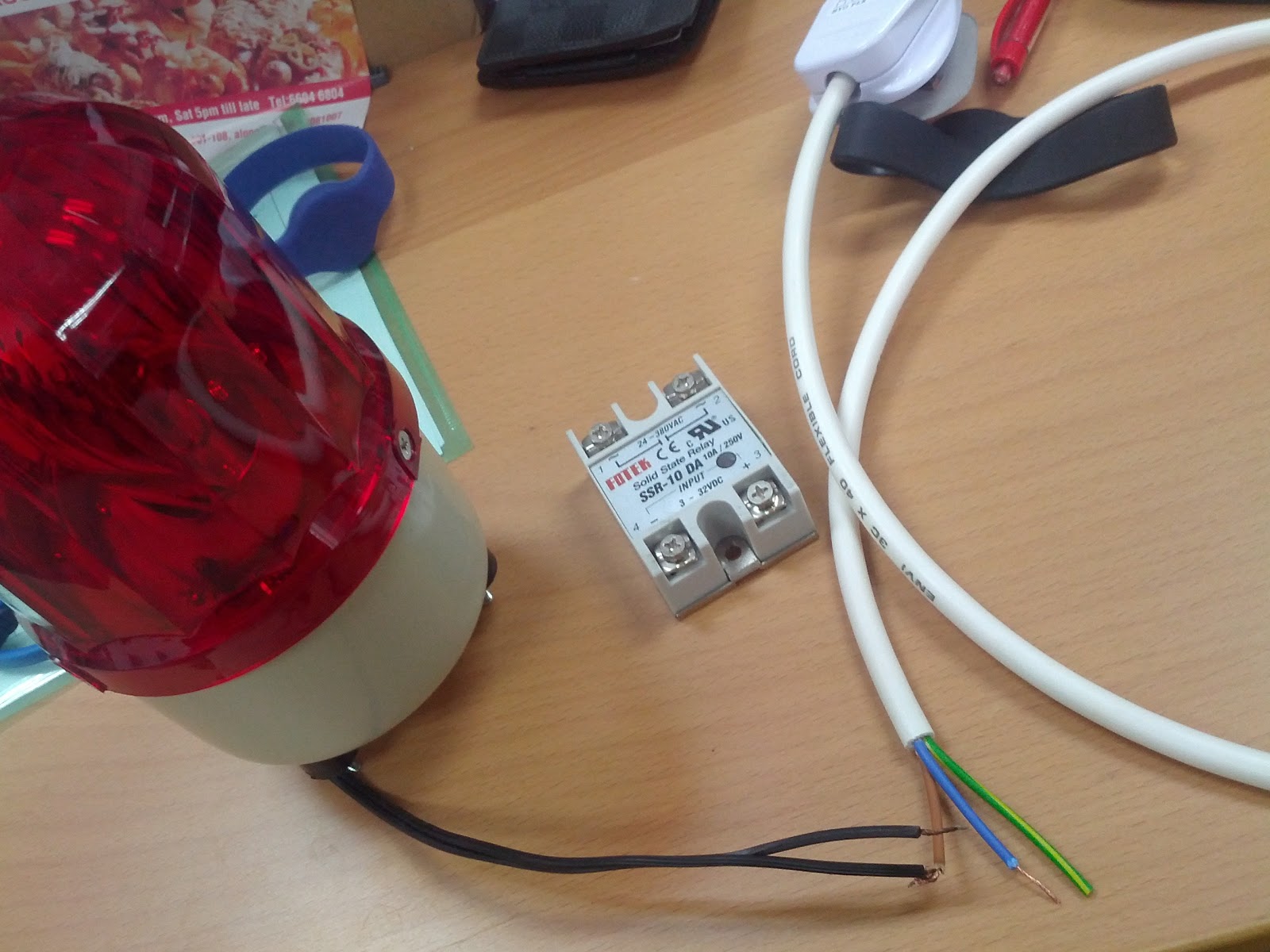
I walked all around Sim Lim Tower and I was getting a bit worried I wouldn’t find the kind of light I wanted. There were a bunch of 12-24V lights that did all kinds of fancy flashing. LED lights, lights that could be programmed to show text… all too futuristic. I needed the old school flashing police light. Finally I found one, and sure enough it was 220V. I had to a bit of wiring, but it worked precisely how I wanted.
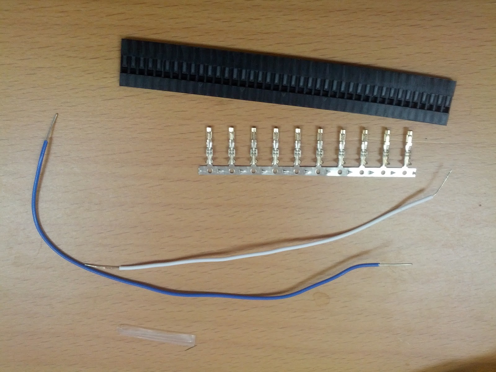
Wiring
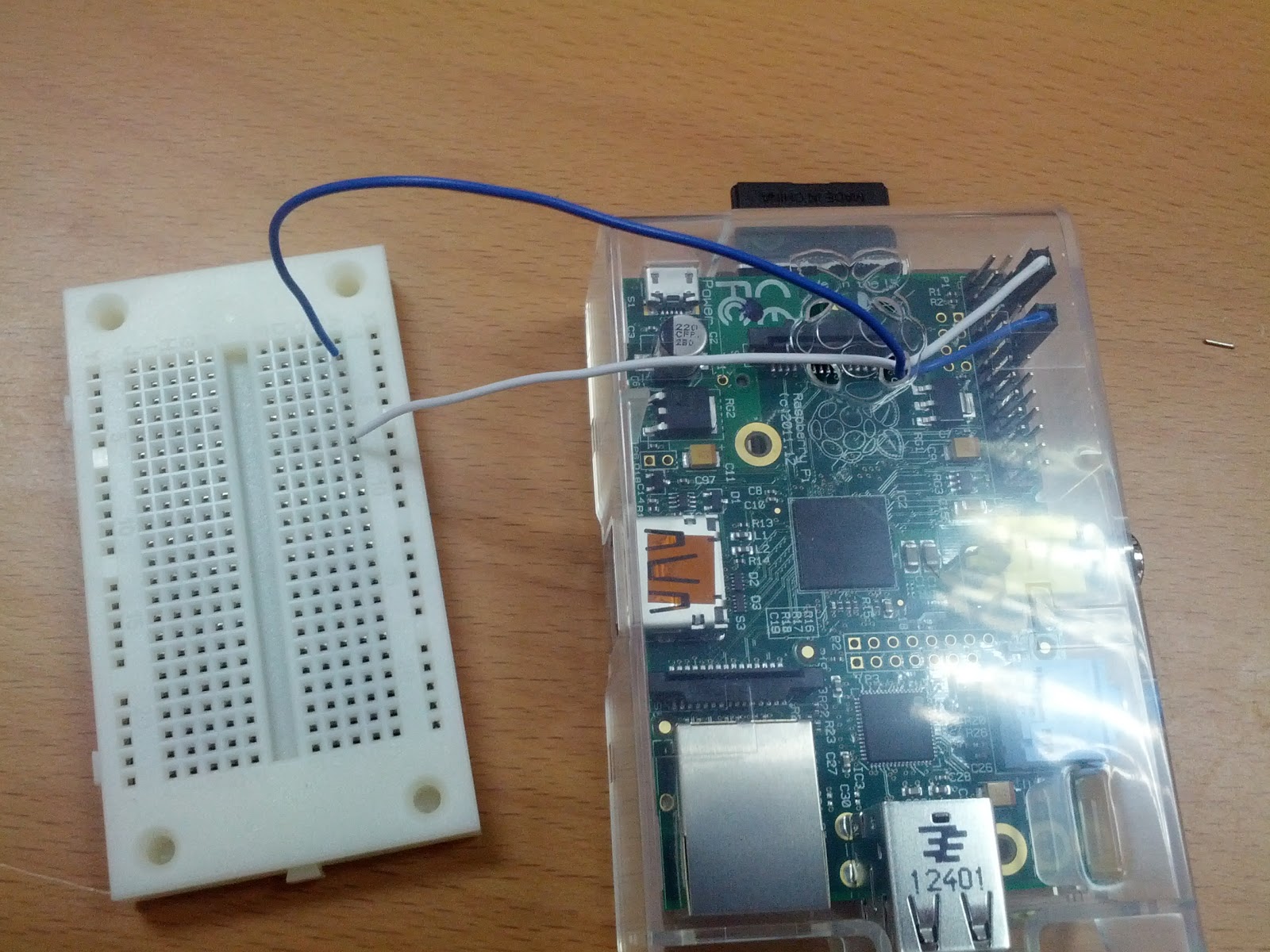
Unfortunately, I wasn’t able to find nice jumper wires like found on this site. So I ended up having to make my own that would nicely connect to the Raspberry Pi’s GPIO pins.
I spent a few hours putting everything together. Sure, it’s no where as complicated as a few Raspberry Pi projects I’ve seen (soon… soon…) but that’s ok. The real work is in the software of this little project.
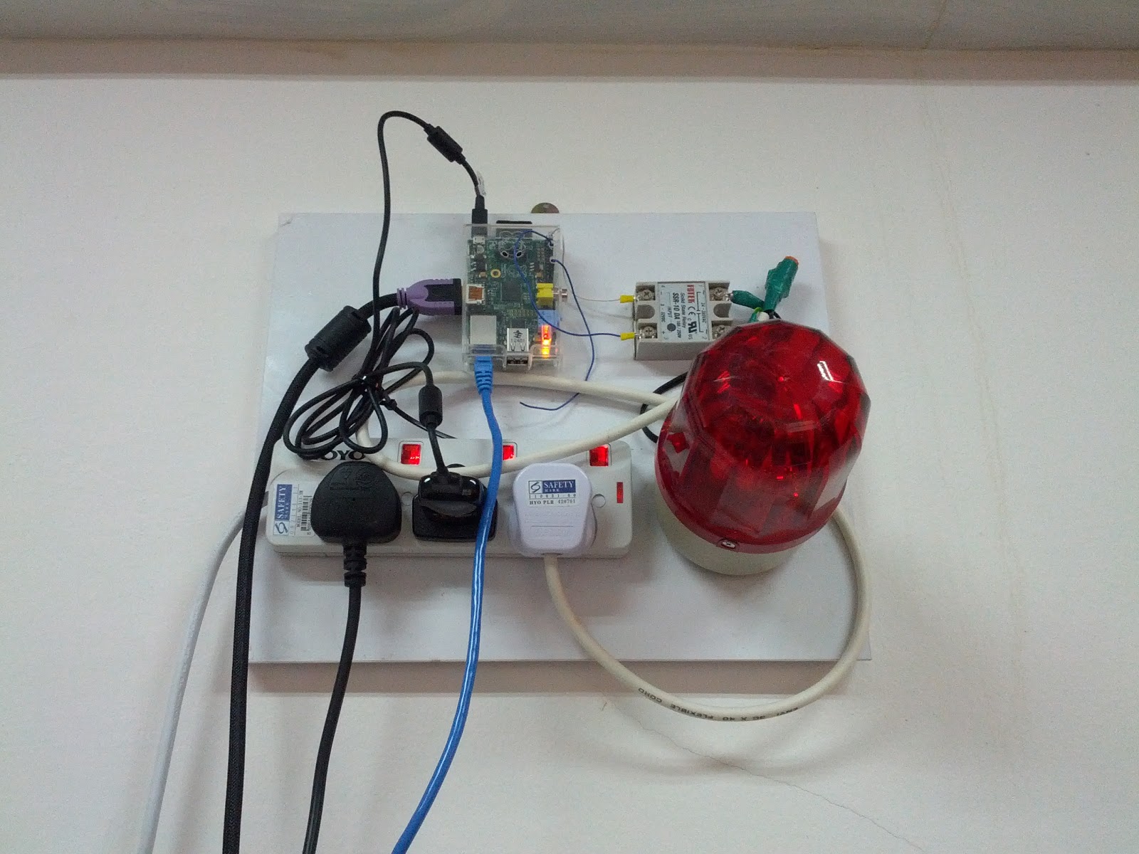
Here you can see the finished product. I need to get a piece of wood to mount everything to it, but essentially it works.
The Software
The software is a long term work in progress. I wrote most everything in PHP / jQuery. The display is connected to the Raspberry Pi over HDMI and is running a locally hosted web page in a full screen Midori that is configured to start up automatically on boot (I find it faster to just reboot than to disconnect my keyboard/mouse, walk over to the Raspberry Pi, plug everything in, and do a refresh of the browser).
The webpage does a simple jquery ajax poll to a php file on the Raspberry Pi that does the following:
- Pulls mail off an imap email account I set up that receives mail from Amazon Cloudwatch (and a few other sources).
- Parses the mails to determine if it’s an alarm or a recovery
- Construct a JSON payload that the webpage gets and then renders the information on the screen.
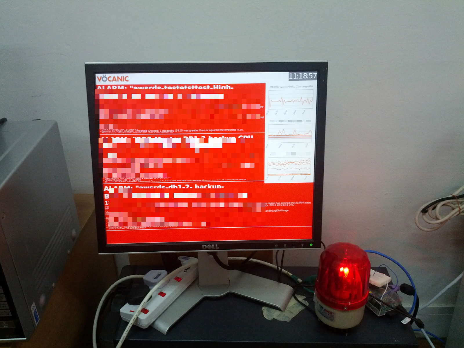
- For dramatic effect (and the whole point of this little project) is if there is at least one alarm status, not only will it show on the minitor with a bright red background - as shown in the photo above - but it will also call a system command to enable one of the GPIO pins that I have connected to the Solid State Relay, that turns on/off the Red Light! When there are no alarm statuses to show, the red light turns off, and the screen goes green. We can all rest now.
I added a few charts so we can monitor, over time, queue sizes, db connections, and other metrics without having to always have a browser window on AWS’s CloudWatch (even though we probably still will) - but hey - charts are cool, too.
Future Plans
Well, first of all, I’m going to have one of our designers take a look at the alarm display since I am design-deficient. Next, I’ll be adding more graphs for the display. But I realized that i need to be careful to not enable too much jQuery fanciness since the Raspberry Pi only sports a 700MHz processor. And no, I won’t be over clocking it anytime soon.
Sound is something I’ll look into next. A colleague suggested adding the James Bond theme when an alarm goes off. I was thinking more of a Nuclear meltdown siren, but we’ll see.
I also thought it would be interesting to try to integrate some sort of light sensor that would help the system determine whether it made sense to turn on the red light or not. No sense having it go off during the late evening if no one is around (we have SMS notifications for that). Sure… I could just do a simple system clock check, but that’s not cool enough.
I’ll post more once I progress!
Update
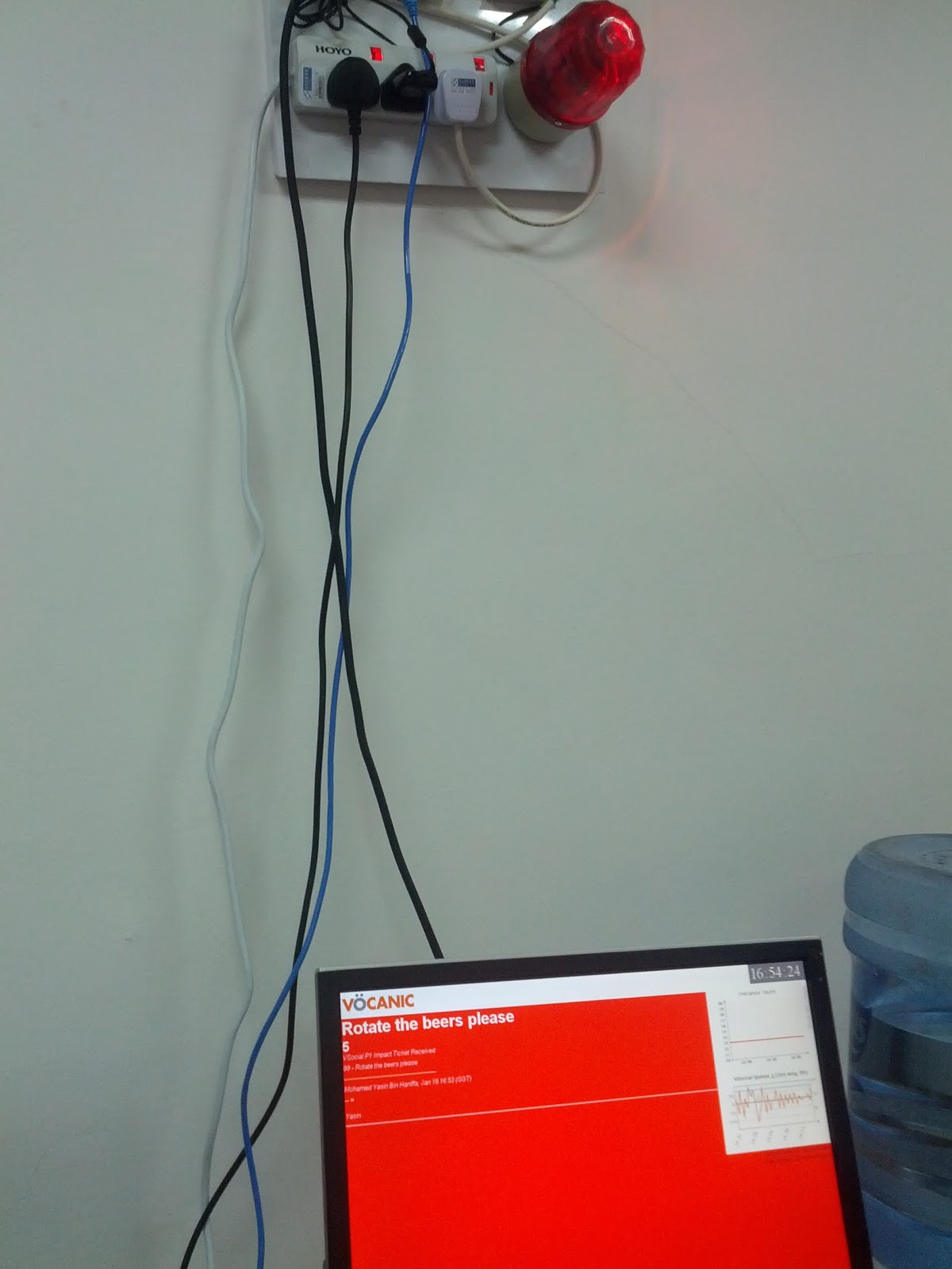
Finished product:
